
Relief Valves and Safety Devices on Cryogenic Tanks
How the cryogenic tank relief valve system works: primary and secondary relief, rupture disc, annular space relief, changeover valve and inspection rules.
KAF Cryogenics13 min read
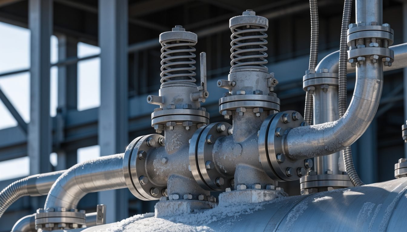
A cryogenic tank relief valve is the device that prevents the vessel from exceeding its maximum allowable working pressure. A complete cryogenic tank does not have one relief device but a system: primary and secondary relief valves on a changeover valve, a rupture disc on the inner vessel, and a separate relief device protecting the annular vacuum space.
Every one of these devices exists because a cryogenic liquid is stored far below its boiling point at ambient conditions. Heat leak is continuous and unavoidable, so pressure rise is the normal state of the vessel, not a fault. The pressure protection system is what keeps that normal rise from becoming a structural failure.
This article explains what each device does, why the changeover valve exists, why relief devices must never be isolated, and what to inspect on the pressure protection system of a used tank before you buy it.
What does a cryogenic tank pressure protection system consist of?
A vacuum insulated cryogenic tank is two vessels in one. The inner vessel holds the cryogenic liquid under pressure. The outer jacket is a vacuum enclosure and is designed for external pressure, not internal pressure. The two need entirely different protection.
A standard arrangement includes:
- A primary safety relief valve on the inner vessel, spring loaded and reclosing, set at or below the maximum allowable working pressure
- A secondary safety relief valve of equal capacity, so one valve can be taken out of service without leaving the vessel unprotected
- A changeover valve carrying both relief valves, arranged so that at least one relief path is always open
- A rupture disc, also called a bursting disc, on the inner vessel as a non reclosing backup device
- An annular space relief device, sometimes called a vacuum jacket relief or a burst plate, protecting the outer jacket
- Vent piping that discharges to a safe location away from personnel and building intakes
Set pressures are established by the manufacturer against the applicable code, PED 2014/68/EU with EN 13458 for static vessels in Europe, EN 13530 and the transport regulations for transportable vessels, or ASME Section VIII for the United States market. They are stamped or recorded in the vessel documentation. They are not field adjustable settings.
What does the primary relief valve do?
The primary safety relief valve is the working device. It opens when vapour space pressure reaches its set pressure, discharges vapour until pressure falls, then reseats. On a tank in normal service, particularly one that is idle or has a fault in its pressure control circuits, this valve may operate periodically. That is the system doing its job.
Two points are often misunderstood by operators:
- The relief valve set pressure is at or below the MAWP of the inner vessel, not at some higher pressure the operator chooses. If a process needs a higher delivery pressure, the answer is a vessel with a higher pressure class, not a different relief valve
- A relief valve that lifts frequently is a symptom, not a nuisance. The usual causes are heat leak from a degraded vacuum, a pressure building regulator stuck open, or an economizer that is not functioning, and each of those should be investigated
Repeated lifting also wears the seat. A valve that has been cycling because of an upstream fault may begin to weep at pressures below its set point, which then looks like a second fault. Fix the cause of the pressure rise and have the valve assessed.
Why is there a secondary relief valve and a changeover valve?
A relief valve is a mechanical device with a spring, a seat and a soft seal. It needs periodic testing and eventually replacement. A pressure vessel in service cannot be left without overpressure protection while that work is done, and emptying and warming a cryogenic tank to change a valve would be a multi day operation.
The changeover valve solves this. It is a three way valve, sometimes described as a dual manifold or transfer valve, with a relief valve mounted on each of two outlets. The internal design means the flow path to at least one relief valve is always open. In the mid position both are connected. It cannot be set to a position that isolates both devices at once.
The operating discipline is simple:
- Move the changeover valve fully to one side to put that relief train in service before removing the other valve
- Never leave the handle in an intermediate position after work, unless the manufacturer instruction specifically defines that position as an operating position
- Both relief valves must have the same set pressure and the same relieving capacity. A replacement is not a matter of finding a valve with the right connection size
- Record the changeover operation, so the maintenance history shows which train was in service and when
The same principle applies to the rupture disc where the tank is fitted with duplicate disc assemblies.
What is the rupture disc for on a cryogenic tank?
The rupture disc is a non reclosing device. It is a thin metal diaphragm that bursts at a defined pressure and then stays open until it is replaced. Its set pressure is above the relief valve set pressure but within the limit the code allows relative to the MAWP, so in a normal overpressure event the relief valve acts first and the disc stays intact.
The disc exists for the events a spring loaded valve may not handle alone:
- A fire case, where external heat produces vapour generation far above normal boil off rates
- A relief valve that fails to open, for example because of ice in the outlet or a mechanical fault
- A rapid pressure excursion where the full relieving area is needed immediately
Because a burst disc does not reclose, the tank will vent its contents through the open disc until the vessel is depressurised. That is intended behaviour. The tank must then be taken out of service and the disc assembly replaced with the correct part, matched to the burst pressure and the holder specified by the manufacturer. A disc from a different manufacturer with a similar rating is not an equivalent part.
A burst disc is also evidence. If you find a burst or replaced disc on a used tank, ask what caused it. The answer belongs in the document dossier.
What protects the annular vacuum space?
This is the device most often ignored, and it protects against one of the more serious failure modes. The annular space between the inner vessel and the outer jacket is under high vacuum. The outer jacket is built to resist that external atmospheric load. It is not a pressure vessel.
If the inner vessel or an internal pipe develops a leak, cryogenic liquid enters the annular space, absorbs heat and vaporises. The volume expansion of a cryogenic liquid turning to gas is very large, so the vacuum space can pressurise quickly. Without a relief path the outer jacket would fail.
The annular space relief device is usually a plate held against a seat by a spring, or a burst plate with an elastomer seal, set to relieve at a low pressure well below anything the jacket could withstand. It also serves a secondary purpose in a fire, allowing the jacket to relieve rather than rupture.
Rules for this device:
- It must never be painted over, taped, sealed with sealant or covered by insulation or cladding
- It must never be blocked by snow, ice, bird nests or stored material leaning against the tank
- It must not be removed to check the vacuum. Vacuum readings are taken through the dedicated evacuation port, not through the relief device
- If it has relieved, the vacuum is gone and the tank is out of service until the cause is found and the insulation system is restored
- On inspection, confirm the device is present at all. On older units it is sometimes found missing after a repair
A jacket relief device that has operated is a strong signal of an inner vessel leak. That is a different problem from a slow vacuum degradation, and it is covered in our article on vacuum loss in cryogenic tanks.
Why must relief devices never be isolated or blocked?
This is the single rule that matters most on a cryogenic installation. A relief device that cannot see vessel pressure, or cannot discharge, provides no protection at all, and the tank gives no outward sign that anything is wrong until pressure has already risen.
In practice, isolation happens in ways that look harmless:
- A block valve fitted upstream of a relief valve and closed to stop a weeping valve, instead of repairing it
- A changeover valve left in a position the manufacturer does not define as an operating position
- A cap, blank or plug fitted to a vent outlet to keep rain out
- Vent piping that has been extended with long or undersized pipe, adding back pressure the valve was not sized for
- A vent outlet that has frozen shut because it points upward and has collected water, or because it discharges into an enclosed space
- An annular space relief device covered during painting or re cladding
Vent piping design deserves attention on any site inspection. Discharge must be to a safe location, away from walkways, doors, air intakes and the tanker filling position, and it must be free draining so condensate cannot collect and freeze. Oxygen and nitrogen discharges also create an oxygen enrichment or depletion hazard at the discharge point, so the location is a safety decision, not just a piping detail.
Where a valve upstream of a relief device is genuinely required by design, the code and the manufacturer instructions define how it must be handled, typically locked or sealed in the open position with a documented procedure. It is never an operator level decision.
How often should relief valves be tested or replaced?
There is no single universal interval, and any supplier who quotes one without asking about your vessel and jurisdiction is guessing. The requirement comes from two places: the applicable code and national regulation for the vessel, and the manufacturer instruction manual for the specific device. For transportable vessels the transport regulations set the periodic inspection cycle, and the relief device work is carried out within that cycle.
What is consistent across regimes is the practice:
- Relief valve set pressure is verified on a test bench by a competent workshop, or the valve is replaced with a new certified unit, at the interval defined by the code and the manufacturer
- Devices are sealed after setting. A broken seal means the setting is no longer verified and the valve must be re certified
- Set pressure is never adjusted in the field to solve an operational problem
- Rupture discs are replaced on a defined interval as well as after any burst, because disc material fatigues under pressure cycling
- Every test, replacement and changeover operation is recorded, with certificates kept in the vessel dossier
- Visual checks between formal intervals cover the vent outlets, the annular space device, corrosion at the valve body and any sign of weeping or ice formation
Fit the relief device schedule into the wider planned maintenance routine for the vessel, alongside the vacuum reading that should be taken every 6 to 12 months. Our cryogenic tank maintenance schedule article sets out how these intervals fit together.
What should you check on the safety devices of a used cryogenic tank?
Pressure protection is one of the areas where a used tank inspection either builds confidence or ends the discussion. Work through the following before committing to a purchase.
- Nameplate MAWP against the set pressure stamped on each relief valve. They must be consistent with each other and with the intended service
- Both relief valves present, of matching set pressure and capacity, with intact manufacturer seals and legible identification
- Changeover valve present and operating smoothly across its full travel, with no evidence that one outlet has been blanked
- Rupture disc holder correctly assembled, with documentation of the disc rating, and an explanation for any replacement
- Annular space relief device present, unpainted, unobstructed and undamaged
- Vent piping intact, correctly routed and free draining, with no caps or improvised extensions
- Certificates for the last relief device test or replacement in the document dossier
- Evidence of the vacuum condition, since a degraded vacuum will keep the relief system working continuously in service
KAF Cryogenics sells certified second hand cryogenic tanks that have passed inspection, non destructive testing and vacuum and pressure testing, and are supplied with a document dossier and written warranty. Where a vessel needs new relief devices, they are specified against the vessel MAWP and the applicable code before the unit is released. New tanks built to specification are also available where the required pressure class or configuration is not in stock.
Frequently Asked Questions
What is the difference between a primary and a secondary relief valve on a cryogenic tank?
There is no functional difference. Both are full capacity relief valves with the same set pressure, mounted on a changeover valve. One is in service while the other is isolated for testing or replacement. The purpose of the pair is that the vessel is never left without overpressure protection while maintenance is carried out.
Why does a cryogenic tank need a rupture disc as well as a relief valve?
The rupture disc is a non reclosing backup device set above the relief valve set pressure but within the limit the code allows. It covers events the spring loaded valve may not handle alone, most importantly a fire case where vapour generation is far above normal boil off, or a relief valve that fails to open. Once burst, the disc must be replaced with the correct manufacturer specified part.
What is the annular space relief device and why does it matter?
It is a low pressure relief device on the outer jacket that protects the vacuum space. If the inner vessel leaks, cryogenic liquid enters the annular space and vaporises, and the resulting pressure would rupture the jacket, which is designed for external pressure only. The device must never be painted over, sealed or obstructed, and if it has relieved the tank is out of service until the cause is found.
Can a relief valve on a cryogenic tank be isolated to stop it leaking?
No. Isolating or blocking a relief device removes overpressure protection from a vessel whose pressure rises continuously from heat leak. A weeping valve must be repaired or replaced through the changeover valve, with the second relief train placed in service first. Any valve upstream of a relief device that is required by design must be locked or sealed open under a documented procedure.
Is a relief valve lifting on a cryogenic tank a fault?
The valve lifting is the system working correctly, but frequent lifting is a symptom worth investigating. Common causes are heat leak from a degraded vacuum, a pressure building regulator stuck open, or an economizer that is not functioning so boil off is vented instead of being used. Repeated cycling also wears the seat and can lead to weeping.
How often must cryogenic tank relief valves be tested or replaced?
The interval is set by the applicable code and national regulation for your vessel and by the manufacturer instruction manual, so it must be confirmed for each tank rather than assumed. What is universal is the method: bench testing or replacement by a competent workshop, sealing after setting, no field adjustment of set pressure, and certificates retained in the vessel dossier.
Where should relief valve vent piping discharge?
To a safe outdoor location away from walkways, doorways, building air intakes and the tanker filling position. The line must be sized so it does not add back pressure the valve was not designed for, and it must be free draining and arranged so water cannot collect and freeze in the outlet. Discharges of oxygen or nitrogen also create an enrichment or depletion hazard at the discharge point.
Do second hand cryogenic tanks come with new relief devices?
It depends on the condition and documentation of the existing devices. At KAF Cryogenics, relief devices on a certified second hand vessel are inspected and, where required, specified and replaced against the vessel MAWP and the applicable code before the unit is released, with certificates included in the document dossier.
Related reading
Need a cryogenic tank with verified pressure protection?
KAF Cryogenics supplies new tanks built to specification and certified second hand vessels that have passed inspection, NDT, and vacuum and pressure testing, with a document dossier and written warranty. Send us your service, volume and pressure class and we will quote against your requirement.
Talk to our team