
Tank Farm Layout: Planning a Site with Multiple Cryogenic Tanks
Plan a cryogenic tank farm layout: product grouping, oxygen separation, tanker access, manifolding, vaporizer placement and drainage. Get a site review.
KAF Cryogenics12 min read
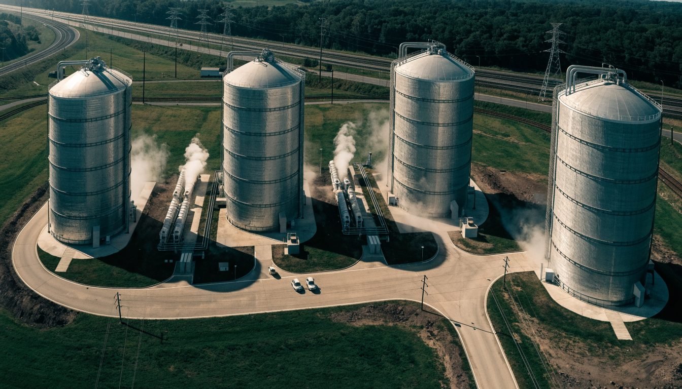
A cryogenic tank farm layout is the site plan that fixes where each tank, vaporizer, fill point and road route sits. It is driven by product grouping, separation from buildings and ignition sources, tanker access and drainage. Separation distances come from national regulation and the applicable standard, so confirm them with the local authority.
Layout is one of the few decisions on a gas site that is effectively permanent. Foundations, buried services, road geometry and the position of the fill point are all expensive to move once concrete is poured. A plant that was laid out for two tanks and later needs five usually ends up with a compromised traffic route or a vessel in a position that limits future work.
This guide walks through the questions a project manager or plant engineer should answer before the first drawing is issued, from grouping vessels by product through to leaving space for expansion.
What is a cryogenic tank farm layout and what does it define?
A tank farm, in this context, is any site holding more than one bulk cryogenic or pressurised gas vessel: an air separation customer site with liquid nitrogen and liquid oxygen, an LNG satellite station, an LPG filling plant, or a distributor's own filling terminal. The layout is the agreed arrangement of all fixed equipment plus the movement routes around it.
A complete cryogenic tank farm layout normally defines the following.
- The position, orientation and foundation of every vessel, with its empty and full weight
- Distances between vessels, and from vessels to buildings, site boundaries, ignition sources and occupied areas
- The fill point for each product and the standing position of the delivery tanker
- Road geometry: approach, turning circle, reversing area and exit route
- Vaporizer positions, spacing and the zone where ice can fall or melt water can collect
- Pipe routes, manifolds, isolation valves and relief device discharge points
- Ground slope, drainage, bunding where required, and surfacing material
- Electrical earthing, bonding points, hazardous area boundaries and lighting
- Space reserved for future vessels and for maintenance access
Everything on that list interacts. Moving a fill point to shorten a hose run can push the tanker into a position where it blocks the site exit. Adding a fourth vessel can close the gap a crane needs for a vacuum service visit years later.
How are separation distances in a cryogenic tank farm decided?
This is the question buyers ask first, and it is the one that cannot be answered with a single number. Separation distances are set by the national regulation that applies at the installation site and by the standard the installation is designed to, and they must be confirmed with the local authority or the notified body handling the permit. There is no universal metre figure that is valid everywhere.
The distance that applies to your site depends on a combination of the following factors.
- The product: oxidising (liquid oxygen), flammable (LNG, LPG), or inert (liquid nitrogen, liquid argon, and, with its own asphyxiation considerations, LCO2)
- The stored quantity and the vessel's maximum allowable working pressure
- What sits on the other side of the gap: a site boundary, a public road, an occupied building, a control room, an air intake, a fixed ignition source or another vessel
- Whether a rated fire wall or barrier is used, which in many national codes allows a reduced distance
- The design standard applied to the vessel, for example EN 13458 for static vacuum insulated cryogenic vessels
- Local planning, fire authority and environmental conditions on the permit
The practical rule for a buyer is straightforward. Do not copy a distance figure from a plant in another country, from a supplier brochure, or from a general article. Have the site plan prepared or reviewed by an engineer competent in the local regime, and obtain the authority's written position before the foundation is cast. Rework at that stage is cheap. Rework after commissioning is not.
KAF Cryogenics supplies the equipment side of that exercise: general arrangement drawings, empty and operating weights, nozzle and connection details, relief device discharge data and the certification file for each vessel. The site design and the permit remain the responsibility of the operator and the local engineer, but they need accurate equipment data to do the work.
How should tanks be grouped by product on a multi tank site?
Group vessels by hazard character first and by operational convenience second. A layout that is convenient but mixes incompatible products creates a permanent risk that no procedure fully removes.
- Inert group: liquid nitrogen and liquid argon. Main hazard is oxygen displacement in enclosed or low lying areas, plus cold burn on contact
- Oxidising group: liquid oxygen. Keep clearly separated from flammable products, from oil and grease, and from combustible surfacing
- Flammable group: LNG and LPG. Vapour behaviour, ignition sources and drainage dominate the layout decisions here
- LCO2: not flammable and not oxidising, but a heavy gas that accumulates at low level, so pits, trenches and basements near the vessel need particular attention
Where a site holds both a flammable product and liquid oxygen, most operators plan them as two distinct areas with separate access, separate fill points and, where the regulation calls for it, a barrier between them. Trying to serve both from one tanker standing position is a common source of layout trouble.
Why must liquid oxygen be kept away from flammable products and organic material?
Liquid oxygen does not burn, but it makes almost everything else burn far more readily. A spill raises the oxygen concentration in the surrounding air and soaks into any porous material below the fill point. Asphalt, oil films, grease, cloth and general site debris all become severe fire risks when saturated with oxygen, and an ignition source that would be harmless in normal air becomes sufficient.
Practical layout consequences for the liquid oxygen area include the following.
- Concrete, not asphalt, under the vessel, the fill point and the tanker standing position
- No oil separators, drains, trenches or pits that could carry an oxygen rich liquid or gas elsewhere on site
- Housekeeping discipline: no stored combustibles, pallets, drums or vegetation in the oxygen area
- Clear separation from LNG, LPG, fuel storage and vehicle parking
- Signage and access control so that maintenance crews do not bring hydrocarbon greases into the area
The mirror problem is oxygen deficiency around nitrogen and argon vessels, where an odourless, colourless gas displaces breathable air in an enclosure. Both effects are covered in more detail in the cryogenic safety basics article linked below.
How much room does a delivery tanker need in a tank farm layout?
Vehicle movement is the layout constraint most often underestimated. A cryogenic road tanker is long, heavy and slow to manoeuvre, and it has to reach the fill point with the hose it carries, not with a hose the site would prefer it to have.
Check these items against the actual vehicles that will serve the site.
- Turning circle and swept path for the longest expected vehicle, checked with a template rather than estimated by eye
- A drive through or one way route where possible, so that reversing past occupied vessels is avoided
- Hose reach from the tanker's standing position to each fill point, allowing for the hose routing rather than the straight line distance
- A level, drained standing area with wheel chocks, an earthing and bonding point and a clear line of sight for the driver
- An unobstructed escape route for the driver away from the fill point in both directions
- Ground bearing capacity along the whole route, not only at the standing position
- Overhead clearance: cables, pipe bridges, canopies and lighting masts
Whether the site is served by a semi trailer, a bobtail or an ISO tank container on a chassis changes all of these numbers. Confirm the vehicle type with the supply contract before fixing the road geometry.
Should multiple cryogenic tanks be manifolded together?
Manifolding means connecting two or more vessels to a common liquid or gas header so they feed the same downstream system. It is a good solution for capacity and redundancy, and a poor one if the isolation philosophy is not designed properly.
Arguments in favour of manifolding include the following.
- One vessel can be taken out of service for inspection or vacuum work while supply continues
- Peak demand can be met from combined capacity rather than by oversizing a single vessel
- A single downstream vaporizer and pressure control train can serve the group
- Deliveries can be sequenced across vessels instead of waiting for one to empty
The design points that must be handled carefully are equally clear.
- Every vessel keeps its own relief devices; a shared header never substitutes for individual protection
- Isolation valves must allow each vessel to be fully separated, locked and drained without disturbing the others
- Pressure differences between vessels can drive liquid from one into another; check valves and an agreed operating procedure prevent this
- Vessels of different maximum allowable working pressure on a common header need explicit protection for the lowest rated unit
- Line sizing and insulation must suit the combined flow, not the flow of a single vessel
When separate lines make more sense
If the vessels serve genuinely different users, hold different products, or belong to different pressure classes, separate lines are usually simpler, cheaper to commission and easier to isolate. Manifolding earns its complexity when the vessels hold the same product at the same pressure class and serve the same demand.
Where should vaporizers be placed in a cryogenic tank farm layout?
Ambient air vaporizers draw their heat from the surrounding air. Placed too close together, or boxed in by walls and equipment, they starve each other of warm air, ice up faster and deliver gas below the required temperature. Placement is therefore a capacity issue, not only a space issue.
- Leave free air circulation on all sides and above, following the manufacturer's spacing guidance
- Keep vaporizers clear of the prevailing downwind path of another vaporizer, so cold discharged air is not recirculated
- Plan duty and standby pairs with a changeover so each unit can defrost; continuous single unit operation is the most common cause of poor performance
- Allow a drained zone below and around each unit for melt water and falling ice, and keep walkways out of that zone
- Keep vaporizers away from building air intakes, occupied doorways, pits and trenches
- Reserve access for de icing, inspection and eventual replacement of a single unit without dismantling the bank
Duty and standby cycling has to be reflected in the layout from the beginning. Retrofitting a second vaporizer bank into a site that reserved no space for it is one of the more common upgrade problems on customer stations.
How should ground, drainage and bunding be planned?
Cryogenic liquid that reaches the ground boils rapidly and produces a large volume of very cold, initially dense gas. The layout decides where that gas goes and where any liquid runs.
- Slope the surface so that a spill runs away from vessel supports, foundations, cable routes and occupied buildings
- Avoid pits, trenches, basements, inspection chambers and enclosed low points near vessels and fill points, since cold dense vapour collects there
- Use surfacing suited to the product, with concrete under liquid oxygen fill and standing areas
- Provide bunding where the national regulation requires it for the product concerned, and confirm the requirement rather than assuming it
- Design foundations for the full operating weight of the vessel plus wind and seismic loads applicable at the site
- Protect vessels, valve assemblies and pipe runs from vehicle impact with bollards or barriers
Foundation design needs accurate figures. Ask the equipment supplier for empty weight, operating weight, support locations and load per support point before the civil design starts.
How much space should you leave for future tanks?
Most gas sites grow. A layout that reserves a defined footprint for one or two additional vessels, with stub connections and a road route that already works for the larger site, costs very little at the design stage and saves a great deal later.
- Reserve a full footprint per future vessel, including its own maintenance and lifting access, not just the shell diameter
- Route the main pipe header so that a tee for a future vessel does not require the existing line to be emptied and cut
- Keep the tanker route valid for the expanded site, not only the current one
- Size the earthing grid, lighting and, where relevant, the gas detection layout for the final configuration
- Record the reserved area on the site plan so it is not gradually taken over by storage or parking
Phasing also depends on how quickly equipment can be delivered. KAF Cryogenics supplies vessels both new to specification and as certified second hand units that have passed inspection, non destructive testing and vacuum and pressure testing, and are sold with a document dossier and a written warranty. Certified second hand units can often be delivered from stock in weeks where new fabrication takes months, which lets an operator bring an expansion phase forward when demand moves faster than the original plan.
Frequently Asked Questions
What separation distance is required between two cryogenic tanks?
There is no single figure that applies everywhere. The required distance is set by the national regulation in force at the installation site and by the standard the installation is designed to, and it depends on the product, the stored quantity, the pressure class and what lies on the other side of the gap. Confirm the applicable distance with the local authority or notified body before the foundation is designed.
Can liquid oxygen and LNG tanks be installed in the same tank farm?
Yes, many sites hold both, but they are planned as separate areas with their own fill points and access, and with the separation or barrier that the national regulation requires. Liquid oxygen sharply increases the ignitability of hydrocarbons and organic material, so mixing the two areas or sharing a tanker standing position is not appropriate.
Do manifolded cryogenic tanks still need individual relief valves?
Yes. Each vessel keeps its own pressure relief protection regardless of how it is connected downstream. A common header does not protect an individual vessel that has been isolated, and isolation valves must be arranged so that a vessel can never be shut in without its relief path.
How much space does an ambient air vaporizer need around it?
Follow the manufacturer's spacing figures for the specific model, because the required clearance depends on the unit's fin geometry and rated flow. The layout principle is constant: free air circulation on all sides, no recirculation of cold discharged air between units, a drained zone for melt water and ice, and a duty and standby arrangement so each unit can defrost.
What ground surface should be used under a liquid oxygen tank and fill point?
Concrete is the normal choice under liquid oxygen vessels, fill points and the tanker standing area. Asphalt and other hydrocarbon based surfacing can absorb spilled liquid oxygen and become a serious fire risk. The area should also be kept free of oil, grease, vegetation and stored combustibles.
What equipment data does a civil engineer need to design tank foundations?
The engineer needs empty and operating weight, support point locations and load per support, overall dimensions, nozzle positions, relief device discharge orientation and the applicable wind and seismic design conditions. KAF Cryogenics provides general arrangement drawings and this data with each vessel so the site design can proceed accurately.
How much space should be reserved for future cryogenic tanks?
Reserve a complete footprint per planned future vessel, including maintenance and lifting access rather than only the shell diameter, and check that the tanker route and pipe header still work in the expanded configuration. Marking the reserved area on the controlled site plan prevents it from being absorbed by storage or parking.
Related reading
Planning a multi tank site?
Send us your product list, demand profile and site constraints. KAF Cryogenics will advise on vessel selection and supply the drawings, weights and connection data your site engineer needs, from new units built to specification or certified second hand units available from stock in weeks.
Request a site equipment review